An Embedded Lcd Display is more than a small screen mounted inside a product. It is a display system designed to work with a device’s electronics, software, and physical controls. You might find one in a handheld meter, a medical monitor, or a factory controller. The glass panel is only part of the story.
A typical module combines an LCD panel, a driver circuit, and a backlight. The host processor sends image data and commands through an interface such as SPI, RGB, or MIPI, depending on the module. The driver converts those signals into instructions the pixels can use. Meanwhile, the backlight illuminates the image from behind. Tiny connectors matter. So do stable power, correct timing, and software configured for the panel’s resolution.
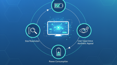
The practical details can be easy to underestimate. A display may look clear on a workbench, then appear washed out under bright sunlight or flicker when its timing is wrong. Design choices also affect power use, viewing angle, touch support, and how easily the module fits into an enclosure. Small errors can become visible problems.
A reliable explanation should distinguish general LCD principles from module-specific requirements. No source material or verifiable expert quotation was supplied, so I won’t invent a named specialist’s words. That limitation matters. This guide will explain how embedded LCD modules receive and show information, what their main components do, and which design details deserve careful checking.
An embedded LCD display is a liquid-crystal screen built into a larger product, such as a handheld meter, control panel, or medical instrument. It presents information as part of that device rather than acting as a separate monitor. The screen may show numbers, icons, menus, or simple graphics.
The liquid crystals do not produce light themselves. In many displays, a backlight shines through the panel, while electrical signals adjust individual pixels to form an image. A controller helps translate data from the host device into screen content. The display may connect through a cable or a compact circuit-board interface. Touch input is optional, not a defining feature.
In a handheld meter, for example, the screen must remain readable under overhead lighting and fit within a narrow case opening. Designers also consider viewing angle, power use, temperature range, and mounting method. A bright backlight can improve visibility, but it may drain a battery faster. The term “embedded LCD” is sometimes used loosely; it can describe different screen sizes and interfaces. Check the device requirements before assuming two displays are interchangeable.
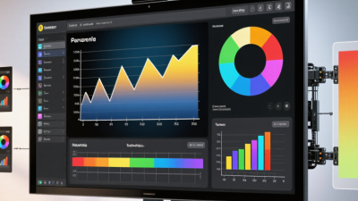
What Is an Embedded LCD Display and How Does It Work?
Key Components and Layers of an Embedded LCD
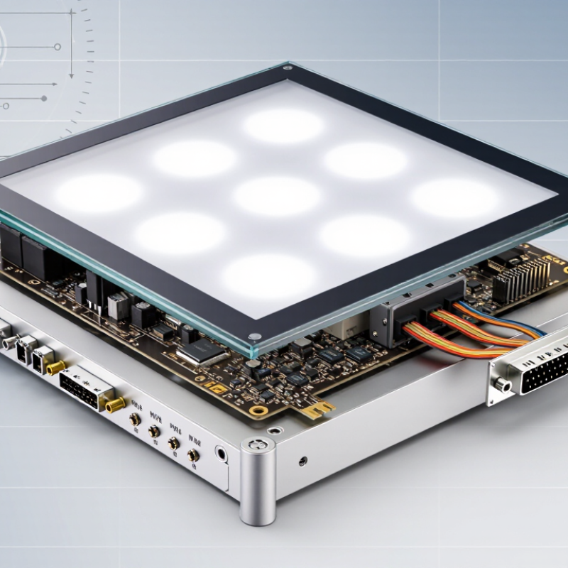
An embedded LCD is a display module built into a larger device, such as an instrument panel or handheld meter. Its image starts in the LCD cell: liquid crystals sit between two glass substrates and change how light passes through crossed polarizers. A backlight, often made from LEDs, supplies the light. Tiny driver circuits control individual pixels, while a flexible cable or board connects the module to the host system. Each layer has a job. Alignment matters.
A cover lens protects the front surface; an optional touch sensor adds input. Beneath them, the LCD cell, polarizers, backlight, and metal frame form a compact stack. Gaps, dust, or uneven pressure can cause visible bright spots or poor contrast. The Global E-waste Monitor 2024, published by UNITAR and the ITU, reports 62 million tonnes of e-waste generated worldwide in 2022; only 22.3% was documented as formally collected and recycled. That figure makes replaceable modules and accessible fasteners worth considering during design. In practice, a thinner stack can be harder to service.
Tips: Check the display under its actual ambient lighting. Confirm connector orientation, operating temperature, and mounting pressure before production. A small prototype often reveals issues that drawings miss. Sometimes, the simplest test is the best one.
| Component or Layer | Typical Position | Common Materials or Parts | Primary Function | How It Contributes to Display Operation |
|---|---|---|---|---|
| Cover lens or front panel | Outermost layer, if fitted | Glass or transparent polymer; may include printed borders or surface treatments | Protects the display surface and can provide a mounting or labeling area. | Transmits the image produced by the LCD. It is a mechanical cover, not the layer that creates the image. |
| Touch sensor (optional) | On or beneath the cover lens | Transparent conductive patterns, commonly based on indium tin oxide (ITO) | Detects touch position on interactive displays. | Reports touch input to a touch controller. It is separate from the LCD’s pixel-driving process. |
| Front polarizer | On the viewing side of the LCD cell | Polarizing film, commonly based on stretched polymer with protective layers | Transmits light with a selected polarization direction. | Works with the rear polarizer and liquid-crystal layer to control how much light exits each pixel. |
| Color-filter glass and black matrix | Front glass substrate of a color LCD cell | Glass with red, green, and blue filter regions and opaque pixel-boundary areas | Creates color subpixels and helps limit light leakage between them. | Each color subpixel filters the backlight into a red, green, or blue component; groups of subpixels form displayed colors. |
| Common electrode | Inside the LCD cell, usually on the color-filter substrate in a basic TFT LCD structure | Transparent conductive film, commonly ITO | Provides one side of the electric field across the liquid-crystal material. | Works with pixel electrodes to establish the voltage that changes liquid-crystal alignment. |
| Liquid-crystal layer | Between the two glass substrates | Liquid-crystal material held in a precisely controlled cell gap | Modulates the polarization and transmission of light. | An applied electric field changes molecular alignment, altering how light passes through the polarizers and controlling pixel brightness. |
| TFT array glass and pixel electrodes | Rear substrate of an active-matrix LCD cell | Glass, thin-film transistors, storage capacitors, and transparent pixel electrodes | Individually controls the voltage applied to each pixel or subpixel. | The transistors switch in response to row signals and charge pixel electrodes using image data from the display driver. |
| Rear polarizer | Behind the TFT glass | Polarizing film with an orientation selected for the LCD mode | Polarizes light before it enters the liquid-crystal cell. | Its orientation relative to the front polarizer allows changes in liquid-crystal alignment to produce visible brightness differences. |
| Backlight unit (for transmissive displays) | Behind the LCD cell | LED light source, light guide or direct-lit arrangement, reflector, diffuser, and brightness-enhancement films | Provides illumination for viewing the image. | Distributes light across the panel; the LCD cell controls how much of that light reaches the viewer at each pixel. |
| Display driver and timing circuitry | At the panel edge or on a connected circuit board | Driver integrated circuits and supporting electronic components | Converts incoming display data and timing signals into row and column drive signals. | Coordinates pixel updates and applies the required electrical signals to the TFT array. The exact interface depends on the module design. |
| Frame, bezel, and interconnects | Around or behind the display assembly | Metal or polymer frame, flexible printed circuits, and electrical connectors | Supports the panel and connects it to the host device. | Provides mechanical alignment and carries power, control signals, and image data between the module and the embedded system. |
An embedded LCD produces an image by controlling how much light reaches each colored pixel. Unlike an emissive screen, it usually relies on a backlight behind the display layers. Light passes through a polarizer, liquid crystal material, color filters, and a second polarizer. The stack is thin, but its alignment matters.
A display controller sends image data and timing signals to the panel. In a TFT LCD, tiny transistors address individual pixel regions, applying measured voltages to their liquid crystals. The crystals change orientation and alter how much light passes through. Red, green, and blue subpixels combine at different brightness levels to create the colors you see. Very small changes matter.
When the backlight is steady, those changing pixels form a readable image. A dark pixel usually blocks more light; it does not produce perfect black, since some light can leak through. Viewing angle, temperature, and panel construction can also shift contrast or color. In an embedded device, the processor and display interface must send data at a rate the panel supports. A bright screen may improve outdoor readability but use more power. The trade-off is not always obvious until the display is tested in its actual enclosure.
An embedded LCD communicates with a host system through an electrical interface and a defined set of commands. The host may be a microcontroller or another computing unit. It sends instructions to configure the display, then transfers image data. Common interfaces include SPI and parallel buses; the right choice depends on screen resolution, refresh needs, and available pins.
During startup, firmware typically resets the display controller and sets parameters such as color format and orientation. Then the host writes pixel values into the controller’s memory, often in rows or small regions. A clock signal helps time each transfer, while data and control signals distinguish image information from commands. Small screens may work well over a slower serial link. High-resolution screens usually need more bandwidth. Details vary by module.
The controller turns received pixel values into electrical signals that operate the LCD panel. The host does not usually control each liquid-crystal cell directly. It sends data, and the controller handles much of the refresh work. Some systems also read touch input through a separate interface. Not every display includes one.
A working image can still hide a communication problem. Check the logic voltage, pin mapping, and initialization sequence before changing application code. A loose connection may produce flickering or missing rows. I have seen timing assumptions become the real issue, even when the wiring looked correct. That is easy to overlook.
An embedded LCD display is built into a product’s control panel or housing, showing information while the device operates. Common types include segment LCDs for fixed symbols and digits, character displays for menus or readings, and graphic displays for icons or changing layouts. TFT LCDs can show color and detailed images, but typically need more power and a more capable controller. The right choice depends on what users must read, not simply on how many pixels fit.
Design starts with the viewing environment. A small screen beside a machine may need wide viewing angles, while a handheld meter used outdoors needs strong contrast in bright light. Backlighting helps indoors and at night, yet adds power draw and can wash out details if poorly matched to the panel. Check operating temperature, connector placement, mounting depth, and the display’s interface before finalizing the enclosure. Details matter. A clear prototype can still become difficult to read behind tinted plastic or at an awkward angle. Test it early. Measure readability under actual lighting, and verify performance across the expected temperature range. Designers sometimes choose a higher-resolution panel before checking whether its text remains legible at the intended distance; that is an easy assumption to revisit.