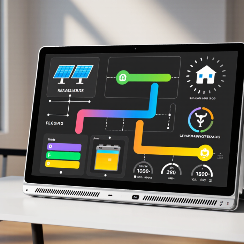
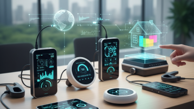
A Hybrid Inverter LCD Display is the practical window into a modern solar power system. It shows how electricity moves between solar panels, batteries, household loads, and the utility grid. Instead of guessing from blinking lights, users can inspect voltage, charging current, battery state of charge, output power, and active warnings on one screen.
Solar educator Will Prowse has often emphasized a closely related principle: “A display is only useful when it helps you understand what the system is doing.” That idea matters here. A well-designed Hybrid Inverter Lcd Display does more than present numbers. It translates complicated electrical behavior into readable information, sometimes using icons, color changes, and simple menus. A sunny afternoon might show strong PV input, rising battery voltage, and reduced grid consumption. At night, the same screen may reveal battery discharge and household demand.
The technology is not perfect. Readings can vary slightly from external meters, especially when sensors are poorly installed or batteries age. Some screens also hide important settings behind unclear menus. That deserves criticism. Reliable operation depends on correct wiring, calibrated sensors, firmware quality, and safe installation by qualified professionals.
This article will explain what a Hybrid Inverter LCD Display is, how its internal monitoring process works, and which figures deserve attention. It will also examine common symbols, warning messages, communication limits, and practical mistakes that can make a healthy system appear faulty.
A hybrid inverter LCD display is the local interface for a system combining solar generation, battery storage, and grid power. It presents live values such as voltage, current, frequency, battery state of charge, and energy flow direction. The International Energy Agency reported 510 GW of renewable capacity additions in 2023, with solar contributing about three-quarters. As installations expand, clear operating data becomes increasingly important.
Its architecture usually includes a microcontroller, sensor inputs, communication circuits, and a segmented or graphical LCD panel. Sensors measure DC input, AC output, temperature, and battery conditions. The controller processes these signals before showing simplified readings on the screen. Protection alerts may include overload, insulation faults, high temperature, and low battery voltage. Some displays also expose operating modes, including self-consumption, backup, and grid support.
The display is not merely decorative. It helps technicians verify wiring, compare expected and actual output, and identify abnormal behavior during commissioning. The IEA PVPS Trends report recorded more than 400 GW of new photovoltaic capacity worldwide in 2023, increasing the need for practical monitoring. Yet LCD readings are not perfect. Sensor tolerances, sampling delays, and poor calibration can distort results. A displayed battery percentage may look precise, but it remains an estimate. Field experience suggests checking critical values with calibrated instruments and reviewing stored fault records. Sometimes, the screen is right. Sometimes, it only reveals where deeper testing should begin.
A hybrid inverter LCD display shows how power moves through the system. It can report battery voltage, charging current, load demand, grid status, and fault codes. The screen does not measure electricity by itself. Internal sensors collect the readings, then a control processor converts them into digital values.
On the DC side, voltage-sensing circuits monitor 12, 24, or 48 V battery banks. Current sensors track charging and discharging flow. These sensors may use shunts or magnetic measurement devices. The processor checks the signals several times per second. It then sends formatted information to the LCD through an internal communication link.
The AC side requires greater care. Isolated voltage sensors sample 120 or 230 V input and output waveforms. Current sensors measure power delivered to household loads. The processor calculates voltage, frequency, watts, and sometimes estimated energy use. The LCD receives only low-voltage data, not direct mains power. That separation matters.
A practical service check compares the screen with a calibrated multimeter. Small differences can occur because of sensor tolerance, wiring loss, or software rounding. The display is helpful, but it is not perfect. A frozen value may indicate a communication fault rather than a battery problem. Technicians should inspect connections, operating temperature, and error history before replacing parts. Never open energized equipment without proper training and isolation procedures.
A hybrid inverter LCD display acts like a small control room for your solar system. It shows solar input, household load, grid flow, and battery direction in near real time. Behind the screen, MPPT tracking adjusts the operating voltage of solar panels. This helps capture more available energy when sunlight changes because of clouds, heat, or partial shade. The display may show voltage, current, and harvested power, making unusual readings easier to notice.
Battery information is equally important. Most screens report charge percentage, charging status, discharge power, and estimated runtime. These figures help users avoid deep discharge and plan energy use during outages. Conversion efficiency commonly ranges from 95% to 99% under suitable operating conditions. However, efficiency is not fixed. Higher loads, low battery voltage, wiring losses, and internal temperature can reduce it. The screen is informative, not perfectly precise. Battery estimates can also drift over time.
Tips: Check the display at similar times each day. Compare solar power with weather conditions and household demand. If MPPT voltage changes sharply, inspect shading and cable connections. Do not judge performance from one reading. A calm pattern across several days is more useful. Personally, I would also record battery percentage manually for a week, because automatic estimates sometimes look convincing but need verification.
A hybrid inverter LCD display turns electrical behavior into readable field information. The frequency line should show 50 or 60 Hz, matching the local grid standard and connected loads. A drifting value may indicate unstable sensing, configuration errors, or a failing control circuit. The IEA PVPS Trends 2024 report records more than 1.6 terawatts of global solar capacity by the end of 2023, making accurate inverter monitoring increasingly important.
Load power is usually shown in watts, kilowatts, or a percentage bar. Watch the number while starting a pump, refrigerator, or power tool. Brief surges can exceed the appliance’s running demand. A display showing 2.4 kW does not always reveal a short 4 kW startup peak. That matters.
Fault codes require the installation manual and measured conditions, not guesswork. Codes may indicate overload, over-temperature, low battery voltage, insulation resistance problems, or grid loss. IEC 62109 safety requirements emphasize protective design for power-conversion equipment, but safe operation still depends on correct installation and testing. The National Fire Protection Association reports that electrical distribution and lighting equipment remain major contributors to home fire losses, so safety alerts should never be bypassed. Turn off the correct isolator, allow stored energy to discharge, and document the displayed code. LCD readings can be imperfect. A loose sensor or outdated firmware may create a convincing but incomplete diagnosis.
A hybrid inverter LCD typically shows AC output frequency, connected load power, fault codes, and safety alerts. The chart below uses realistic typical running-power values for common household loads.
LCD load power is normally displayed in watts and may rise sharply when motors, compressors, or heating elements start. Frequency indicates the AC cycle rate: 50 Hz produces 50 cycles per second, while 60 Hz produces 60 cycles per second. Fault codes and safety alerts vary by inverter design, so the user manual should be consulted before servicing.
What Is a Hybrid Inverter LCD Display and How Does It Work?
A hybrid inverter LCD display shows how energy moves between solar panels, batteries, the grid, and household loads. It may show charging current, battery voltage, output power, temperature, and operating mode. During normal operation, symbols can change quickly as sunlight and demand fluctuate. A small sun icon may appear, then disappear under a passing cloud.
IEC 62109 focuses on safety requirements for power converters used in photovoltaic systems. IEC 62477-1 addresses safety for power electronic converter systems more broadly. These standards help guide protection against electric shock, fire, excessive temperature, and abnormal operation. They do not necessarily prescribe one universal warning message or screen design. Therefore, an LCD warning should be read with the equipment manual and installation records.
A message such as “Overtemperature” suggests that internal heat has reached a protective limit. “Insulation Fault” may indicate unsafe leakage from the photovoltaic circuit. “Battery Overvoltage” can require immediate inspection of settings, wiring, or battery conditions. Do not treat a warning as a diagnosis. It is an important clue.
In field inspections, I check the displayed code, event time, ventilation space, cable connections, and measured voltage. A display can be useful, but it can also be misunderstood. Icons are sometimes too small. Translation may be unclear. Turn off unsafe equipment only according to approved procedures, and use qualified personnel when live circuits may be present.
| LCD Display Category | Typical Displayed Message or Indicator | What the Display Represents | Likely Operating Condition | Recommended User Action | Safety Relevance Under IEC 62109 and IEC 62477-1 | Typical Status |
|---|---|---|---|---|---|---|
| System initialization | Starting, Self-Test, Initializing | The inverter is checking internal control circuits, measurements, communication links, and operating limits before power conversion begins. | The unit has recently been switched on, restarted, or recovered from a temporary interruption. | Wait for the startup sequence to finish. Do not disconnect protective conductors or remove covers during operation. | Supports controlled startup and helps prevent operation before essential monitoring and protective functions are active. | Normal |
| Grid unavailable | Grid Lost, No Utility, Grid Fault | The inverter has detected that the utility voltage or frequency is absent or outside its permitted operating range. | Utility failure, open AC isolator, loose wiring, or abnormal grid conditions. | Check whether the utility supply and AC disconnect are available. A qualified person should inspect wiring if the message remains. | Related to safe interface with the utility network, including disconnection behavior during abnormal grid conditions. Exact thresholds depend on the applicable product and grid requirements. | Protective |
| Anti-islanding trip | Island Detected, Anti-Islanding, Grid Disconnect | The inverter has stopped exporting energy because it detected a condition consistent with an energized but isolated utility circuit. | The utility supply is interrupted or voltage and frequency are unstable. | Do not attempt to bypass the protection. Wait for the authorized reconnection conditions or contact a qualified installer. | Displays a safety-related shutdown condition intended to prevent unintended energization of a disconnected utility circuit. | Protective |
| PV input overvoltage | PV Overvoltage, DC High, PV Voltage Error | The measured photovoltaic input voltage is above the inverter's allowed DC input limit. | Incorrect string design, excessive series-connected modules, or unusually low temperature increasing open-circuit voltage. | Turn off the system using the prescribed shutdown sequence. Have a qualified person measure the PV strings and verify the design voltage. | Important for protection against hazardous DC stress, insulation breakdown, component damage, and excessive touch-voltage risk. | Fault |
| PV insulation or ground fault | Insulation Fault, PV Isolation Low, Ground Fault | The insulation resistance between the PV circuit and protective earth is below the permitted level or a leakage path has been detected. | Damaged cable insulation, moisture ingress, connector failure, or an improperly installed PV array. | Stop operation if instructed by the equipment manual. Do not touch exposed conductors; arrange testing by a qualified electrical professional. | Supports protection against electric shock, fire, and unintended current paths in the DC system. | Fault |
| Battery low state of charge | Battery Low, Low SOC, Battery Discharging Limited | The battery energy level has reached a configured reserve or minimum operating threshold. | Extended discharge, insufficient solar generation, high household demand, or an intentional backup reserve setting. | Reduce nonessential loads and allow charging from an approved source. Follow the battery manufacturer's operating limits. | Helps prevent operation outside the battery system's permitted voltage and state-of-charge range; the display alone does not replace battery protection. | Caution |
| Battery overtemperature | Battery Temperature High, Battery Temp Alarm | A temperature sensor has detected that the battery or battery compartment is above its configured limit. | Insufficient ventilation, high ambient temperature, excessive charging or discharging current, or a battery cooling problem. | Stop high-power operation if required, improve ventilation, and seek qualified service if the warning persists. | Temperature monitoring helps limit thermal stress and supports protective shutdowns for energy-storage equipment. | Fault |
| Battery communication failure | BMS Comm Loss, Battery Communication Error | The inverter is not receiving required data from the battery management system, such as voltage, temperature, or current limits. | Disconnected communication cable, incorrect protocol settings, loss of auxiliary power, or a battery management system fault. | Do not operate the battery outside approved settings. Check only accessible connections and contact a qualified installer if communication is not restored. | Prevents charging or discharging when required battery protection information is unavailable. | Fault |
| Output overload | Overload, Output Power Limited, Load Too High | The connected load demand exceeds the inverter's continuous or temporary output capability. | Too many appliances operating simultaneously, motor startup current, or an incorrectly sized backup circuit. | Switch off nonessential loads and restart only according to the operating instructions. Have circuit sizing checked if the issue repeats. | Helps prevent excessive conductor, switching-device, and power-electronic component heating. | Caution |
| Internal overtemperature | Inverter Overtemperature, Derating, Thermal Shutdown | The internal temperature has reached a level at which output power must be reduced or operation must stop. | Blocked ventilation, direct solar exposure, high ambient temperature, dust accumulation, or prolonged high load. | Keep ventilation openings clear and allow the unit to cool. Do not open the enclosure; arrange service if the warning recurs. | Thermal monitoring and protective limitation reduce the risk of overheating and component damage. | Caution |
| Residual current or leakage detection | RCMU Fault, Residual Current, Leakage Detected | The inverter has detected residual current or an abnormal current relationship that may indicate leakage to earth. | Damaged insulation, moisture, appliance leakage, wiring problems, or a system event during startup. | Follow the shutdown instructions and have the AC and DC circuits tested by a qualified person. | Provides monitoring associated with protection against electric shock and insulation-related hazards; the required protective arrangement depends on the installation. | Fault |
| Surge protection indication | SPD Alarm, Surge Protection Fault | A surge protective device status contact or internal monitoring circuit reports that protection may be disconnected or degraded. | A transient event has operated the protective device, or the protection module requires replacement. | Arrange inspection and replacement by a qualified person. Do not assume the inverter itself is protected from future surges. | Provides information about a protective component; it does not eliminate the need for correct earthing, bonding, and installation-level surge protection. | Caution |
| Grounding or protective conductor issue | PE Fault, Ground Error, Earth Connection Error | The inverter has detected an abnormal protective-earth connection or a condition affecting its grounding reference. | Disconnected protective conductor, incorrect wiring, installation fault, or a measurement anomaly. | Stop and isolate the system only using the prescribed procedure. A qualified electrician must verify protective continuity and polarity. | Protective earthing and fault-current paths are fundamental safety considerations addressed by power-converter safety requirements. | Fault |
| Communication or meter error | Meter Error, CT Error, Communication Timeout | The inverter is missing data from an energy meter, current transformer, battery, or other control device. | Incorrect wiring direction, communication interruption, configuration error, or device power loss. | Check the displayed operating mode and avoid relying on automatic load-control or zero-export functions until communication is restored. | Accurate measurement supports safe control decisions, but a communication warning may not itself indicate an electrical hazard. | Caution |
| Firmware or configuration warning | Parameter Error, Configuration Required, Firmware Mismatch | A required setting is missing, invalid, incompatible, or outside the permitted range. | Commissioning error, incomplete update, incompatible accessory, or restoration of factory settings. | Do not change grid, battery, or protection parameters without authorization. Refer to the installation documentation and qualified service personnel. | Prevents operation with settings that could conflict with protective functions, operating limits, or installation requirements. | Caution |
| Normal hybrid operation | PV Charging, Battery Charging, Battery Discharging, Bypass, Backup Mode | The display shows the active energy path among photovoltaic generation, battery storage, utility supply, and loads. | The inverter is operating within configured voltage, current, frequency, temperature, and power limits. | Monitor power flow and state of charge. Use the documented shutdown procedure before maintenance. | Operational information improves user awareness, while safety functions remain dependent on the complete certified design and installation. | Normal |
| Standards note: IEC 62109 and IEC 62477-1 establish safety requirements and protective principles for power converters and power electronic converter systems. They do not prescribe one universal LCD layout or one exact warning vocabulary. Actual messages, thresholds, symbols, and reset procedures vary by equipment design, system configuration, and applicable installation or grid requirements. Always follow the specific inverter manual and use qualified personnel for electrical testing or service. | ||||||